- +86 13837949030 +86 15890619536
- info@lymcbearings.com
- Bearing Zone,Luoxin Industrial Cluster, Luoyang City,Henan Province,China

Time:2026-11-16 03:01:18 Source:LYMC Slewing Bearing
Preload is the one adjustment in a crossed roller bearing mounting that shapes stiffness, rotational accuracy and service life at the same time. Applied correctly, it removes internal clearance and keeps every roller in contact with both raceways, so load is shared instead of concentrated on a few rollers. Applied incorrectly, it raises friction torque, heat and fatigue, and can destroy a bearing that was perfectly specified on paper. This guide explains the main preload methods used with crossed roller bearings, how each is applied in practice, and how to choose and verify the right one for machine tool, rotary table, robot and indexing applications.
A crossed roller bearing uses cylindrical rollers arranged at 90 degrees to each other in a single raceway, alternating around the ring. This design carries radial, axial and moment loads simultaneously, which is why it is common in rotary tables, robot joints and precision indexers. The trade-off is that the roller-to-raceway fit is extremely sensitive to clearance.
Every rolling bearing has a deflection curve. While internal clearance remains, the first portion of an applied load simply moves the rings until the rollers touch the raceways, and the bearing shows almost no resistance. Only after that dead band does the bearing become stiff. Preload eliminates the dead band by applying a permanent internal load before the external load arrives, so the bearing responds immediately and proportionally from the very first newton.
The result is a stiffer system, but stiffness is not the only benefit. Preload also:
The gain is not unlimited. Beyond an optimal point, additional preload increases friction torque and heat far faster than it increases stiffness, and that surplus heat eventually reduces life. Selecting a method is therefore as much about controlling the amount of preload as about creating it.
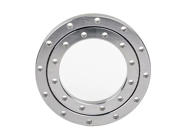
The most common approach for crossed roller bearings is axial clamping with an end cap, flange or bearing cover that presses the outer or inner ring against a shoulder. The bearing is preloaded by the clamping force of evenly tightened bolts, and the amount is adjusted by the axial dimension of the shoulder, the cap, or a lapped spacer between them.
Because bolt torque is difficult to convert into a precise axial force, this method is usually set by dimension rather than by feel. Bolt patterns must be tightened in a controlled sequence so the ring is not distorted. This is the standard solution for rotary tables where the bearing is a large thin-section ring and the customer machines the housing shoulder to a defined height.
Shims are thin precision spacers placed between the bearing ring and its shoulder or end cap. Changing the shim stack changes the axial position of the ring and therefore the preload. Shims offer good repeatability, are inexpensive and can be adjusted in the field without remachining parts.
The main limitation is resolution. Each shim adds a discrete step, so achieving a very fine preload usually requires a lapped shim or a combination of thin foils. Shim stacks also add a compliant interface, which is acceptable in most rotary axis designs but not ideal where maximum stiffness is required.
With thin-section crossed roller bearings, a controlled interference fit on the inner or outer ring provides preload without any axial hardware. Pressing the ring onto the shaft or into the housing changes its diameter slightly and closes the internal clearance around the circumference.
This method gives excellent stiffness and a compact design, but it demands tight control of the fit. Wall thickness, ring rigidity and housing material all affect how much preload the interference produces, so the same fit that works in a steel housing behaves differently in aluminum or cast iron. Interference preload is generally not adjustable after assembly and is best reserved for high-volume, well-characterized designs.
Disc springs, wave springs or coil spring packs apply a defined axial force instead of a fixed displacement. The advantage is thermal tolerance: if the shaft grows relative to the housing during operation, the spring absorbs the movement while keeping preload nearly constant.
Spring preload is well suited to applications with wide temperature swings or long shafts, and it is often used in measuring instruments and high-speed spindles. Its weakness is lower stiffness compared with a rigid clamped stack, because the spring itself deflects under load.
A threaded nut, set screw or tapered wedge allows preload to be dialed in during assembly and re-adjusted later. This is useful for prototypes, repair work and machines where the bearing may be replaced in the field.
The risk is that threaded elements can creep or loosen under vibration. Where this method is used, locking features such as a second nut, thread-locking compound or a captured wedge are essential to keep preload stable through the service interval.
| Method | Stiffness | Adjustability | Thermal behaviour | Typical use |
|---|---|---|---|---|
| End cap / flange | High | Low after assembly | Rigid, sensitive to growth | Rotary tables, indexers |
| Shim | High | Moderate, stepwise | Rigid | Machine tools, retrofit |
| Interference fit | Very high | None | Rigid | Production assemblies |
| Spring | Moderate | Good | Self-compensating | Wide temperature range |
| Screw / wedge | Moderate to high | High | Depends on locking | Prototypes, field service |
Many real assemblies combine two methods. A typical precision rotary axis uses an interference fit on the inner ring plus an end cap with a lapped spacer on the outer ring, which gives both radial rigidity and a fine axial adjustment.
Choosing a method is only half the task. The preload must be set to a target and then confirmed. These factors decide the target value:
For verification, engineers typically measure starting or running friction torque on a slowly rotating assembly, check axial and radial runout with a dial indicator, and confirm that displacement under a known test load stays within the calculated range. Any of these checks will reveal a bearing that is loose, or one that has been over-preloaded and is running hot.
Suppliers such as LYMC often publish recommended fits, clamping dimensions and preload classes for each bearing series, and those values should be the starting point rather than an afterthought.
It depends on the application, but most precision rotary axes are set with a light preload that just removes internal clearance. Heavier preload is reserved for high-stiffness, low-speed applications. The manufacturer's preload class and the calculated axial displacement are the reliable references.
Yes, when the ring is thin-walled and the housing or shaft fit is tightly controlled. However, the amount of preload depends heavily on housing material and wall thickness, so it should be verified by measurement rather than assumed.
Only when it is excessive. A moderate preload improves load sharing and can extend life; too much preload raises contact stress and heat, which shortens life and increases friction torque.
Shim or adjustable screw preload is usually the practical choice, because both allow the preload to be reset on site without remachining the housing shoulder.
Preload in a crossed roller bearing is a controlled compromise between stiffness, accuracy, friction and life. End caps and interference fits deliver maximum rigidity for production rotary tables, shims offer a practical field-adjustable middle ground, springs handle thermal movement, and threaded adjusters suit prototypes and repairs. Whichever method is chosen, the deciding factor is not the hardware but the discipline of setting a defined target and verifying it with torque and runout measurements before the machine goes into service.