- +86 13837949030 +86 15890619536
- info@lymcbearings.com
- Bearing Zone,Luoxin Industrial Cluster, Luoyang City,Henan Province,China

Time:2026-10-12 03:01:56 Source:LYMC Slewing Bearing
Selecting the correct slewing bearing is a critical engineering decision that directly affects equipment performance, safety, and longevity. A miscalculation in sizing can lead to premature failure, costly downtime, or even catastrophic structural damage. This guide provides a systematic approach to slewing bearing sizing, helping you align technical parameters with your specific application requirements. Whether you are designing new equipment or replacing an existing bearing, understanding the fundamentals of load calculation, geometry, and environmental considerations is essential. With decades of industry expertise, LYMC offers precision-engineered slewing bearings tailored to diverse industrial needs, ensuring reliability and optimal operational efficiency.
The first and most critical step in slewing bearing sizing is accurately determining the loads the bearing will encounter during operation. Slewing bearings typically handle three primary load types: axial load (thrust), radial load, and tilting moment. These loads are rarely static; they vary with dynamic conditions such as acceleration, deceleration, wind, and payload shifts.
Axial load acts parallel to the bearing's axis of rotation. For example, in a crane, the weight of the crane itself plus the lifted load creates an axial force. When calculating, include both the static weight of the rotating structure and any live loads. Use the maximum expected load in worst-case scenarios.
Radial loads act perpendicular to the bearing axis. These are often generated by side forces from wind, rope tension, or misalignment. Many slewing bearings are designed primarily for axial loads and tilting moments, but radial loads must still be accounted for—especially in applications like excavators or wind turbines where lateral forces are significant.
The tilting moment is the most complex and often the dominant factor in slewing bearing selection. It results from loads applied at a distance from the bearing center, creating a bending moment that tries to tilt the rotating platform. The formula for tilting moment is load multiplied by the distance from the bearing center (lever arm). Always consider the combination of all loads acting simultaneously to determine the worst-case tilting moment.
Tip: Use safety factors of 1.25 to 2.0 depending on application criticality and operating conditions. LYMC recommends consulting their engineering team for custom load analysis using finite element methods.
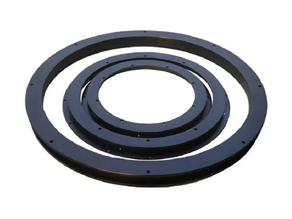
Once loads are established, the next step involves matching bearing geometry to your equipment’s physical constraints and performance requirements. The primary parameters include bearing outside diameter, inside diameter, raceway geometry, and cross-sectional dimensions.
The bearing’s outer diameter (OD) and inner diameter (ID) are determined by the available mounting space and the required clearance for bolts or welds. However, increasing the diameter also increases the lever arm for tilting loads, which can actually reduce load capacity per unit size. A larger bearing may be necessary for high tilting moments but may also increase weight and cost.
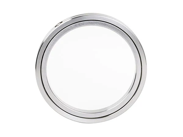
Slewing bearings typically use ball or roller raceways. Four-point contact ball bearings are common for light to moderate loads and offer low friction. Crossed roller bearings provide higher rigidity and load capacity for heavy-duty applications. The choice affects not only load handling but also stiffness, rotational accuracy, and maintenance intervals. LYMC offers both types with optimized heat treatment and hardened raceways for extended service life.
While most slewing bearings operate at low rotational speeds (under 10 rpm), the duty cycle—number of oscillations or rotations over the equipment’s life—significantly influences bearing sizing. High-frequency oscillation can accelerate raceway wear, requiring a larger bearing or specialized lubrication system. For continuous rotation applications, consult the dynamic load rating and expected L10 life.
Operating conditions greatly affect bearing performance and must be integrated into the sizing process. Common environmental factors include temperature, contamination, humidity, and exposure to chemicals or saltwater.
High temperatures can degrade lubricants and cause thermal expansion, altering internal clearances. Low temperatures increase lubricant viscosity and may embrittle steel. LYMC provides sealed bearings with high-temperature grease options for applications ranging from -40°C to +150°C. Always specify the operating temperature range during sizing.
Dust, mud, sand, and moisture are common in construction, mining, and marine environments. Proper sealing is essential. Lip seals, labyrinth seals, or double-seal configurations prevent ingress and retain lubricant. The bearing size must accommodate the chosen seal geometry without compromising load capacity.
The interface between the bearing and the supporting structure is as important as the bearing itself. Use high-strength bolts with proper preload, and ensure the mounting surfaces are flat and rigid. Any deflection in the supporting structure will impose additional loads on the bearing. LYMC’s design team can provide custom mounting recommendations, including bolt patterns and torque specifications, to ensure optimal load distribution.
LYMC has been a trusted name in slewing bearing manufacturing for over a decade, delivering solutions that balance performance, cost, and longevity. When you work with LYMC, you gain access to:
By choosing LYMC, you ensure that your equipment receives a slewing bearing engineered to match its exact needs, reducing the risk of premature failure and extending maintenance intervals.
To simplify the sizing process, follow this practical checklist when specifying your next slewing bearing:
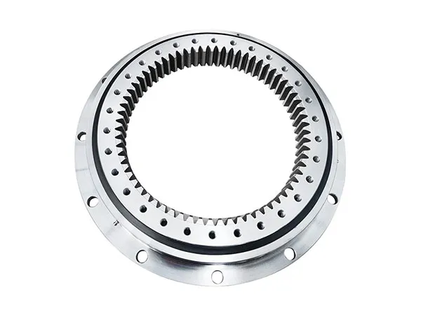
Slewing bearing sizing is not a one-size-fits-all exercise. It demands a thorough understanding of load mechanics, environmental conditions, and equipment dynamics. By following this guide and leveraging LYMC’s engineering expertise, you can select a bearing that delivers consistent performance, maximizes uptime, and reduces total cost of ownership. For complex applications or unique requirements, always involve a specialist early in the design phase. Accurate sizing today prevents expensive replacements tomorrow.