- +86 13837949030 +86 15890619536
- info@lymcbearings.com export@lymcbearings.com
- Luoxin Industrial Cluster, Luoyang City,Henan Province,China
Time:2025-05-13 03:02:32 Source:LYMC Slewing Bearing
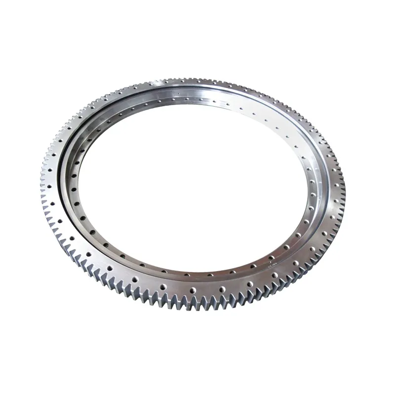
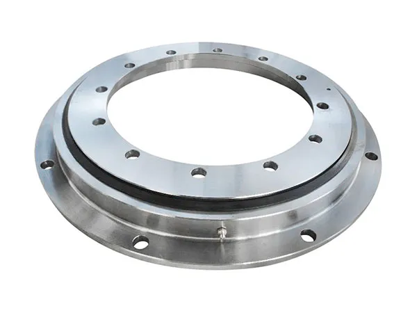
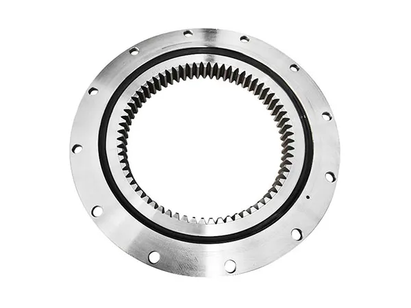
A flange slewing bearing (also called a flanged rotary bearing or slew ring) is a specialized bearing designed to handle axial, radial, and moment loads simultaneously while enabling smooth rotational movement. It is widely used in heavy-duty applications such as cranes, excavators, wind turbines, and industrial turntables.

How it Works - Step-by-Step:
Components: Like any slewing bearing, a flange type consists of:
Inner Ring: One of the main structural rings. It has a precisely machined raceway for the rolling elements. It might have the flange, or it might be plain. It can also have gear teeth (internal or external) or be gearless.
Outer Ring: The other main structural ring, also with a raceway. It might have the flange, or it might be plain. It can also have gear teeth or be gearless. Crucially, at least one of the rings must have a flange for it to be a "flange slewing bearing".
Rolling Elements: These are typically balls (often in a "four-point contact" arrangement) or cylindrical/tapered rollers (often in a "crossed roller" arrangement). They sit between the inner and outer ring raceways and allow low-friction rotation.
Cage/Spacers: Keep the rolling elements evenly distributed and prevent them from contacting each other.
Seals: Protect the internal components from contaminants (dirt, water, debris) and retain the essential lubricant (grease).
The Flange(s): The key feature – the projecting rim with mounting holes on either the inner ring, outer ring, or sometimes both.
Mounting: This is where the flange makes a difference. Instead of needing to bolt through the main body of the bearing ring (which requires a very rigid and precisely machined mounting surface), the flange provides an easier attachment point.

The structure that mates with the flanged ring simply needs a flat surface to meet the flange.
Bolts are passed through the holes in the flange and secured into the mating structure (e.g., the base of an excavator or the rotating platform of a medical scanner).
The non-flanged ring (if there is one) is mounted conventionally to the other structure.
Load Transmission:
Axial Load: Transmitted vertically through the rolling elements from one ring to the other.
Radial Load: Transmitted horizontally through the rolling elements.
Tilting Moment Load: This complex load is resisted by the geometry of the raceways and the rolling elements acting in opposition across the bearing's diameter. The secure bolting (enabled by the flange) ensures the bearing stays firmly attached while resisting this tipping force.
Rotation:
Often, one of the rings (flanged or not) has gear teeth (internal or external). A pinion gear driven by a motor engages these teeth.
When the pinion rotates, it drives the geared ring, causing it to rotate relative to the other ring.
The rolling elements roll smoothly within the raceways, allowing this relative rotation with minimal friction, even under heavy load.
If the bearing is gearless, rotation is imparted by other means directly to the rotating structure.

Simplified Mounting: Often easier and faster to install as the bolt holes are readily accessible on the flange.
Potentially Lighter Supporting Structure: The mounting forces are transferred through the flange, which might allow for a less massive or complex design for the immediate supporting structure compared to non-flanged types where bolts might go directly into thick ring sections.
Space Saving: Can sometimes allow for more compact overall machine designs.
Precise Alignment: The flange can help ensure accurate positioning during assembly.
In summary, a flange slewing bearing works on the same fundamental principles as any slewing bearing (using rolling elements between two rings to handle complex loads and allow rotation), but it incorporates one or more flanges with mounting holes on the rings to provide a specific, often simplified, method of attaching the bearing to the surrounding structures.